A Practical Workflow for Designing
Better Detection and Segmentation Models
By Dr. Ali Khan | Occulins
September 24, 2026
There is a meaningful difference between tuning a model and designing one. Tuning is adjusting, changing learning rates, augmentation parameters, model scales — within an existing architecture to improve performance. Designing is different. It starts from a specific understanding of why the current architecture fails and produces a targeted structural change that addresses that failure.
Most practitioners tune. Researchers design. The distinction matters not because one is superior to the other, but because they answer different questions. Tuning asks: how do I get the most out of this architecture? Designing asks: what does this architecture not do that it should, and how do I build something that does it?
This post describes a practical workflow for the second question — one that applies equally to object detection and semantic segmentation, and that is grounded in the same process that produces publishable architecture improvements.

Figure 1 — The four-step architecture design workflow: Identify limitation → Propose module → Evaluate → Iterate. The cycle is not linear, evaluation frequently reveals that the proposed module addresses one limitation while exposing another, leading directly to the next iteration. Each cycle produces one testable, attributable improvement.
The first step is diagnosis, and it is the step most people rush. The temptation is to see that the baseline model does not perform well enough and immediately start looking at architectural changes or training improvements. The problem with this approach is that it produces solutions before the problem is understood precisely enough to know whether they address it.
A well-identified limitation is specific, quantified, and mechanistically explained. It answers three questions: what exactly is failing, how much is it failing by, and why is the current architecture producing this failure.
How to Identify Limitations Precisely
Precise limitation identification requires looking at your baseline model's failures in structured ways rather than just inspecting random prediction images.
Stratify by the dimension that matters. If you suspect an object size problem, compute per-size-bucket AP, objects below 16px, 16 to 32px, 32 to 64px, above 64px. If you suspect a positional bias, compute per-region AP, top-left, top-right, centre, bottom quadrants. The stratification reveals exactly where the failure is concentrated.
Trace the failure to an architectural component. Once you know that objects below 32px fail disproportionately, trace why. Where in the network does spatial information for these objects become insufficient? At what layer does the feature map resolution drop below what is needed to represent these objects? This tracing connects the observed failure to a specific architectural mechanism.
Quantify the failure precisely. A limitation stated as "the model struggles with small objects" is not actionable. A limitation stated as "74% of objects below 16px are missed, compared to 18% for objects above 32px, producing a 56 percentage point gap" is actionable. The quantification is what makes the remedy verifiable, after proposing and implementing a module, you measure whether this specific gap has closed.
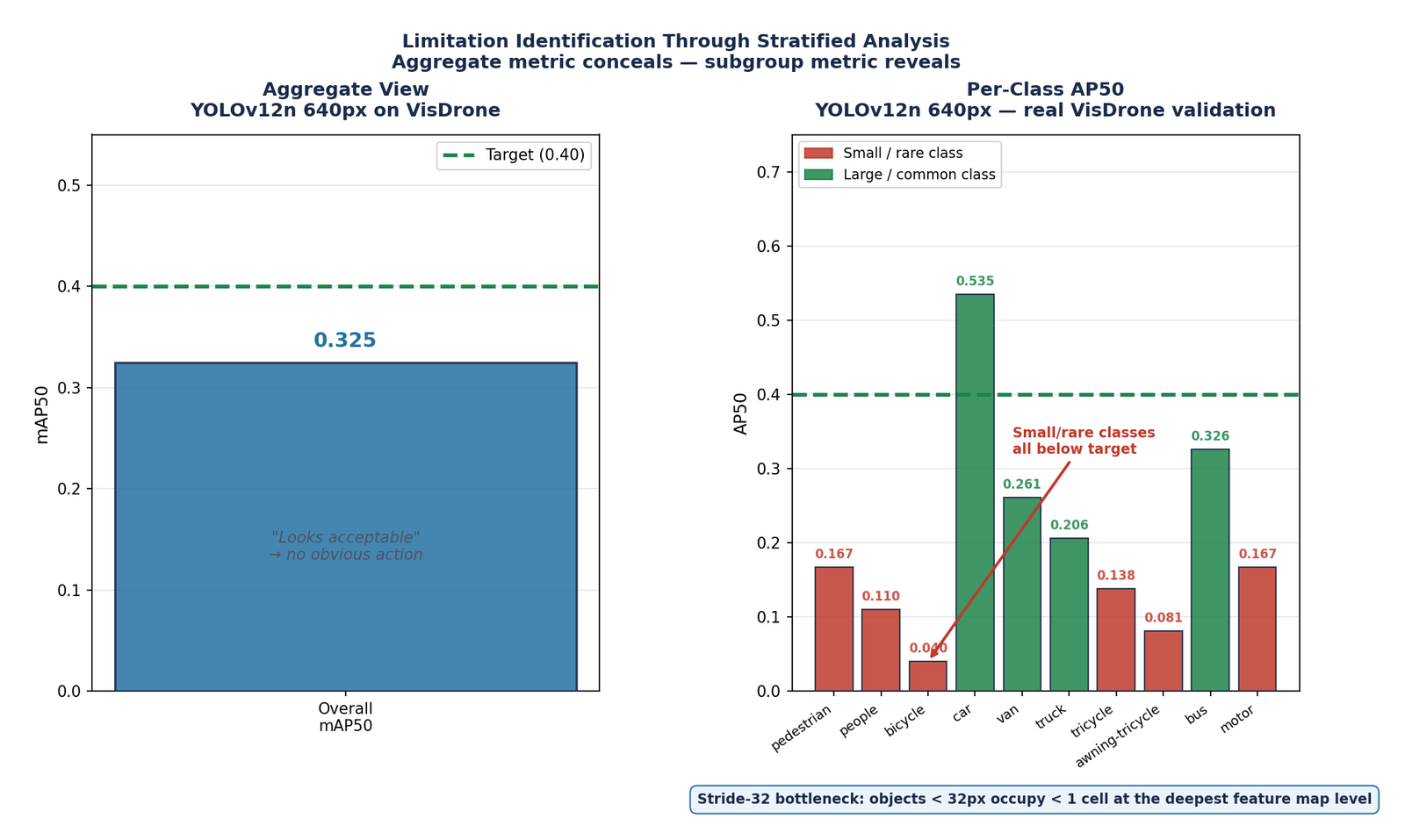
Figure 2 — Limitation identification through stratified analysis on VisDrone. Left: overall mAP50 of 0.325 looks acceptable. Right: per-class AP50 from real YOLOv12n 640px validation reveals that small and rare classes (red) all fall well below the performance target while large classes (green) perform strongly. Car AP50 = 0.535, bicycle AP50 = 0.040, a 13× gap that the aggregate metric conceals entirely. The architectural mechanism is the stride-32 bottleneck: objects below 32px occupy less than one feature map cell at the deepest layer.
A good module proposal follows directly from a good limitation identification. If you have identified that the bottleneck feature map lacks spatial resolution for small objects, the module proposal addresses that specific gap. If you have identified that the decoder loses boundary precision during upsampling, the module proposal addresses that specific mechanism.
The key word is targeted. A module that addresses a specific limitation is testable, you can measure whether it closes the identified gap. A wholesale architecture redesign is not testable in the same way because you cannot attribute performance changes to specific structural decisions.
What Makes a Module Proposal Strong
It addresses exactly one limitation. A module that claims to improve feature extraction, multi-scale representation, and decoder precision simultaneously is not targeting a limitation, it is redesigning the architecture. Each module should have one primary mechanism and one primary expected effect. This is what makes the ablation study possible.
It has a mechanistic justification. "I added an attention mechanism and performance improved" is an observation, not a design. "I added a channel attention mechanism to the encoder because the identified limitation was weak channel-level feature discrimination between visually similar classes at the bottleneck" is a design. The justification connects the module's mechanism to the identified limitation.
It is as simple as possible while addressing the limitation. Architectural complexity that is not justified by a specific limitation adds parameters and computational cost without a clear expected benefit. The simplest module that addresses the identified limitation is the right module. Complexity can always be added in the next iteration if the limitation proves harder than expected.
Detection vs Segmentation Module Design
The module design process is identical for both tasks, but the failure modes that drive module proposals differ in characteristic ways.
In detection, the most common identified limitations are: insufficient feature map resolution at the bottleneck for small objects (addressed by resolution increase or feature pyramid modifications), weak feature integration across scales (addressed by neck architecture changes), and class confusion between visually similar objects (addressed by attention or feature refinement modules in the backbone).
In segmentation, the most common identified limitations are: encoder feature redundancy producing inefficient parameter use (addressed by efficient block designs that replace standard double-3×3 convolutions), insufficient multi-scale contextual information at the bridge (addressed by dilated convolution modules or pyramid pooling), and boundary precision loss during decoding (addressed by upsampling method changes or skip connection refinements).
Evaluation in this context means more than running the validation script. It means designing an experiment that provides evidence for or against the specific claim your module makes that it addresses the identified limitation, and doing so in a way that a reviewer would accept as methodologically sound.
The Ablation Study
The ablation study is the primary evidence for a module's contribution. It isolates the module's effect by comparing performance with and without the module while holding everything else constant. A well-designed ablation answers three questions: does the module improve overall performance, does it specifically improve the metric associated with the identified limitation, and does it improve more on the failure cases identified in Step 1 than on cases where the baseline already performs well.
The table below shows a real ablation from the VisDrone experiments covered in this blog series. Every number comes from an actual validation run using the standard evaluation protocol (conf=0.001). The "Avg Small AP50" column tracks the identified limitation, the average AP50 of the five smallest and rarest classes in VisDrone: bicycle, people, pedestrian, tricycle, and awning-tricycle.
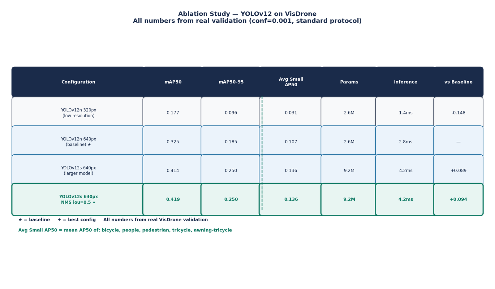
Figure 3 — Ablation study from real YOLOv12 VisDrone experiments. Each row changes one variable. The baseline is YOLOv12n at 640px. Moving to YOLOv12s (larger model) improves overall mAP50 by +0.089. Adding NMS iou=0.5 (threshold adjustment) provides a further +0.005 at no compute cost. The Avg Small AP50 column tracks the identified limitation, small and rare class performance across all configurations. All numbers from real validation runs.
| Configuration | mAP50 | mAP50-95 | Avg Small AP50 | Params | Inference |
|---|---|---|---|---|---|
| YOLOv12n 320px (low resolution) | 0.177 | 0.096 | 0.031 | 2.6M | 1.4ms |
| YOLOv12n 640px (baseline) | 0.325 | 0.185 | 0.107 | 2.6M | 2.8ms |
| YOLOv12s 640px (larger model) | 0.414 | 0.250 | 0.136 | 9.2M | 4.2ms |
| YOLOv12s 640px + NMS iou=0.5 (best) | 0.419 | 0.250 | 0.136 | 9.2M | 4.2ms |
What a Complete Evaluation Includes
An ablation table is necessary but not sufficient for a complete evaluation. A complete evaluation also includes:
Evaluation on multiple datasets. A module that works on one dataset may be overfitting to that dataset's specific characteristics. Evaluating on two or three datasets with different properties, different object densities, different domain, different acquisition conditions, provides evidence that the improvement generalises.
Comparison with published baselines. The ablation shows that your module improves over your baseline. The comparison with published work shows that the resulting model is competitive with the state of the art. Both are necessary for a complete evaluation.
Negative results included. An ablation table that includes only configurations where your module wins is not credible. Include configurations where the module does not help or where it makes things worse. These negative results strengthen the overall evidence by demonstrating that the evaluation was conducted honestly and that you understand the conditions under which the module is and is not beneficial.
A single iteration of this workflow produces one verified improvement, a module that demonstrably addresses one identified limitation. In practice, a publishable architecture improvement typically requires three to five iterations before the resulting model is competitive with the state of the art across multiple datasets and metrics.
What the Next Iteration Looks Like
After completing the evaluation in Step 3, you have two pieces of information that drive the next iteration: the residual limitation and the revealed trade-offs.
The residual limitation is what remains after the proposed module has been applied. If the module addressed small object detection by improving bottleneck feature resolution, the next question is: what does the model now fail on that it did not fail on before, and what was it already failing on that the module did not address? The answer to this question defines Step 1 of the next iteration.
The revealed trade-offs are the costs the module introduced, additional parameters, additional inference time, or reduced performance on a different metric or subgroup. The next iteration may need to address one of these trade-offs rather than a new limitation, if the trade-off is unacceptable for the deployment constraints.
Knowing When to Stop
Iteration does not continue indefinitely. It stops when one of three conditions is met: the model meets the performance target for the application, the remaining limitations are not addressable without a fundamental redesign, or the computational cost of further improvements exceeds the deployment budget.
Knowing which condition applies requires honest evaluation at each iteration rather than continuing to add modules in the hope that performance will eventually meet the target. A model with five modules addressing five limitations is not inherently better than a model with two modules addressing the two most significant limitations. Module count is not a proxy for quality.
What Makes This Different from Hyperparameter Tuning
Hyperparameter tuning — adjusting learning rate, batch size, augmentation intensity, anchor sizes, operates within a fixed architecture. It finds the best operating point for what the architecture can do. This workflow changes what the architecture can do.
The practical difference is that tuning has a ceiling defined by the architecture's structural limitations. When you have tuned every accessible parameter and performance still does not meet the target, the only remaining option is to change the architecture which requires understanding precisely why the current architecture fails, which is Step 1 of this workflow.
This is why the workflow begins with limitation identification rather than module proposal. Tuning cannot tell you what the ceiling is or why it exists, only that it exists. Analysis of the baseline's failures is what reveals the ceiling and its causes, which is the prerequisite for designing past it.
The Honest Difficulty
This workflow is described in four steps, which makes it sound more sequential and more contained than it is in practice. The honest picture is messier.
Limitation identification is rarely complete on the first attempt. You identify what you think is the primary limitation, propose a module, run the evaluation, and discover that the improvement is smaller than expected, which usually means the limitation was either misidentified or was only one of several contributing factors. The evaluation result sends you back to the analysis step with more information than you had before.
Module proposals that seem logically inevitable from the limitation analysis sometimes do not work, not because the reasoning was wrong but because the network finds other ways to compensate for the limitation that make the proposed module redundant, or because the proposed module introduces a different failure mode that outweighs its benefit. These results are informative but they take time and compute to discover.
Ablation studies that are designed to be complete frequently reveal unexpected interactions between modules, one module that performs well in isolation performs differently when combined with another. Understanding these interactions requires additional ablation rows that were not planned in advance.
The workflow does not eliminate this messiness. It structures it so that each iteration produces a testable claim, generates evidence for or against that claim, and produces information that makes the next iteration more informed than the current one. That structuring is what distinguishes research from experimentation without direction.
This Workflow in Practice
The detection and segmentation series on this blog has covered every component of this workflow across eleven posts. Identifying baseline limitations through stratified evaluation (Blogs 4, 7, 8, 10). Proposing targeted remedies through understanding of architectural mechanisms (Blogs 3, 6). Evaluating properly through ablation design and metric selection (Blogs 7, 8). Iterating through the feedback between evaluation and the next design decision (Blog 11).
Book 3 of both the Detection and Segmentation series documents a complete application of this workflow, from baseline analysis through module design through published ablation results. The detection series Book 3 covers the design of a multi-module architecture for aerial object detection. The segmentation series Book 3 covers the design of DFF-UNet, published in IEEE Transactions on Instrumentation and Measurement in 2025. Both books show the full four-step cycle applied to a real research problem, including the iterations that did not work and what they revealed.
Selected implementations, supporting utilities, and companion resources related to this article are available through the Blog 12 Companion Resources page .
Companion Resources Included
- Ablation table template (real VisDrone data)
- Limitation identification framework
- Ablation design checklist
If you are working on a detection or segmentation architecture problem, trying to push past a performance ceiling that tuning cannot address, the workflow described in this post is where to start. The diagnosis step is almost always the most valuable investment.
Feel free to reach out through Occulins Contact if you are working through any stage of this process and want to discuss the approach for your specific problem.